CHAPTER VII
Manufacturers of Power Cutters
Six COMPANIES in the United States manufacture power paper cutting machines of the single knife, guillotine, general purpose type. Each company offers several sizes and models to meet the requirements of plants of various sizes.
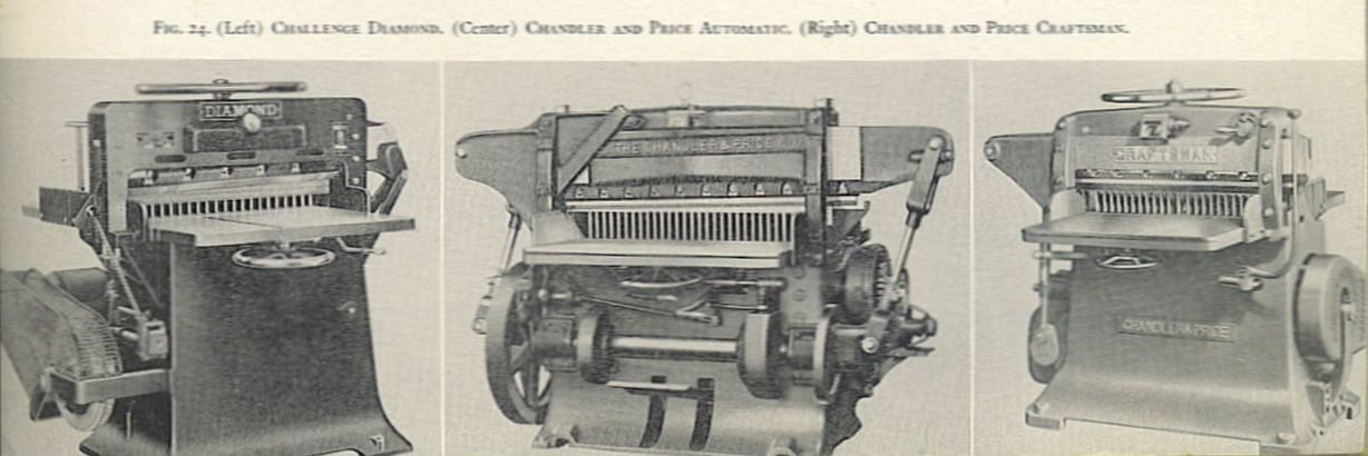
Challenge Diamond. The Diamond cutter is made in three sizes: 30 1/4, 34 1/2 and 36 1/2 inches, hand clamp with a maximum pile height of 33./4 inches. The clamp plate may be detached to make a minimum cut of inch. The machine features a double-motion starting lever to prevent accidental starting of the knife. As optional equipment, it may be fitted with a two hand starting device, a safety mechanism to prevent repeat strokes of the knife, and a fluorescent table light and tape magnifier.
The knife is pulled through the stock pile by a crank and lever assembly at the right of the machine. Adjustment of the blade to the cutter stick is made with two cap screws extending vertically through each end of the knife bar. Complete directions for operation. maintenance and adjustment may be found in the manual entitled Directions for Erectinz and Adjusting Diamond Paper Cutters, obtainable from the manufacturer, Challenge Machinery Company, Grand Haven, Michigan.
C and P Craftsman. Craftsman cutter is a 34 1/2 inch machine, hand clamp with a maximum pile height of 3 inches. The clamp plate may In removed for a minimum cut of inch. The knife is pulled through the paper by a crank and lever located left of the machine frame. Adjustment of the knife to parallel the cutter stick is made by an eccentric lever located on the outer front frame of the machine. Vertical adjustment of the knife stroke is done with a turnbuckle on the drawbar lever.
Standard equipment includes a double-motion control lever to prevent accidental starting of the knife. Optional equipment includes a two hand starting control, a safety device to prevent repeat strokes of the blade, and an illuminated magnifying glass for tape reading. Complete directions for operation, adjustment and maintenance may be found in Instructions for Operating and Adjusting the New 34Y2 Inch Craftsman Paper Cutter, Chandler and Price Company, 6000 Carnegie Avenue, Cleveland, Ohio.
C and P Automatic. In addition to the hand clamp machines the Chandler and Price Company makes three sizes of automatic clamp cutters: 39and 50 inch. The machines are built for heavy duty work with a one-piece base casting and a knife pulled throught the stock with drawbars at each end attached to a single crankshaft. The knife is adjusted with turnbuckles on each drawbar. Maximum pile height is 6 inches. Minimum cut with clamp plate removed is 1/2 inch.
Standard equipment includes an illuminated tape magnifier, two hand starting control, knife non-repeat safety device. and centralized oiling tubes. Optional equipment is the Bowen Oiling System and left and right hand extension tables for the cutter bed. Directions for operation, maintenance and adjustment may be obtained from the Chandler and Price Company.
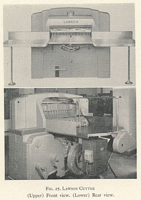
Lawson. The Lawson machines are built in three sizes: 38 inch, with an automatic friction clamp; and 46 and 52 inch, which have an automatic hydraulic clamp. Maximum pile height is 6 inches. Minimum cut is inch with clamp plate removed. Standard equipment includes a tape magnifier and table light, two hand operating controls, knife non-repeat mechanism, knife changing device, and a safety overload release. As optional equipment the 46 and 52 inch cutters may be equipped with a power driven back gauge or an automatic spacer with mechanically operated stops. Complete directions for operation. adjustment and maintenance of each size cutter may be found in manuals entitled Instructions for the Lawson Cutter, issued by the E. P. Lawson Company, 426 West 33rd Street, New York, New York.
National. This cutter uses hydraulic power for its movements. It is made in two sizes, 36 inch and 57 inch. The 36 inch machine has hydraulic power applied to the knife and clamp, with a hand operated back gauge. The 57 inch machine is completely hydraulic, with back gauge, clamp and knife controlled from valve levers underneath the front of the cutter table. Clamp pressure is easily adjusted, with working pressure indicated on a dial at the front of the machine.
Maximum pile height is 534 inches. Minimum cut is 1/2 inch with the clamp plate removed. Standard equipment on the machines includes a tape magnifier and table light, side table extensions, a quick-change knife bar that is self-adjusting to the cutting stick, two hand operating controls, knife non-repeat device, and an automatic overload release valve. Detailed instructions for operation and care of the machines may be obtained from the manufacturer, the Frank M. Hill Machine Company, 5o School Street, Walpole, Massachusetts.
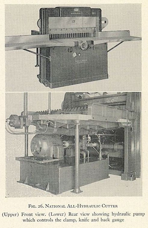
(Upper) Front view. (Lower) Rear view showing hydraulic pump
which controls the clamp, knife and back gauge
Seybold Model CBA. The Model CBA is a 36 inch machine with an automatic clamp which exerts pressure through compression springs. Adjustment to three different pressures is achieved with the addition or removal of collars to the springs. Maximum pile height is 5 inches. Minimum cut is Y4 inch by removing the clamp face plate.
The knife is pulled through the paper by a crank and drawbar on the right of the machine. Eccentrics at each end of the knife bar provide for quick adjustment of the knife to the cutter stick. Standard equipment includes the tape magnifier and table light, overload safety release, two hand starting controls, and knife non-repeat device. Right and left hand extension tables are optional. Directions for operation, adjustment and maintenance are obtainable from the Harris-Seybold Company, 4510 East 71st Street, Cleveland, Ohio.
SeyboId Heavy Duty 40 Inch. The automatic friction type clamp on this cutter is conveniently adjusted with a wrench, the pressure being indicated on a shadow gauge at the front of the machine. The knife is pulled through the paper with drawbars at each end of the knife bar. The knife is adjusted to the cutter stick with a turnbuckle on each drawbar and without the use of wrenches. Maximum pile height is 6 inches, minimum cut inch with clamp plate removed.
One of the features of the Heavy Duty 4o and the larger Sixty Series Seybold cutters is a unique system of changing knives, pictured and described in figure 27a. Standard
The clamp is held down with the foot treadle and two knobs are threaded into holes in the clamp front side. The clamp is then lifted until the knol.bs support the knife while the bolts arc being removed. When the knife is free, the clamp is lowered until the knife clears its holding bar. Handles are threaded into the blade and it is lifted out of the machine. Replacement of the knife is done by placing it on the knobs, aligning the bolt holes, then lifting the knife into position with the knife bar by raising the clamp.
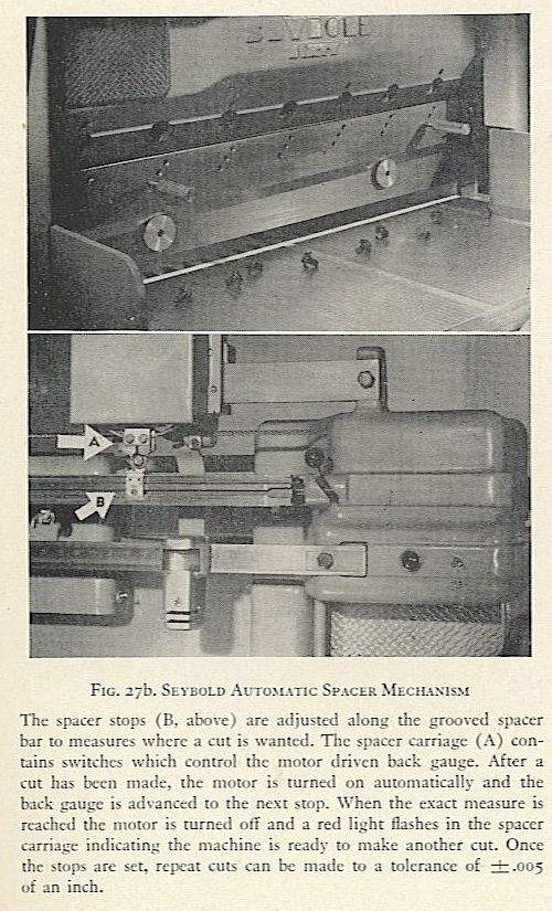
FIG. 27b. SEYBOLD AUTOMATIC SPACER MECHANISM
The spacer stops (13. above) are adjusted along the grooved spacer bar to measures where a cut is wanted. The spacer carriage (A) contains switches which control the motor driven back gauge. After a cut has been made, the motor is turned on automatically and the back gauge is advanced to the next stop. When the exact measure is reached thc motor is turned oti” and a red light flashes in the spacer carriage indicating the machine is ready to make another cut. Once the stops are set, repeat cuts can be made to a tolerance of plus or minus.005 of an inch.
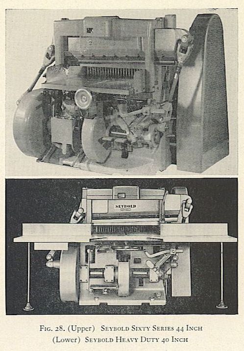
FIG. 28. (Upper) SEYBOLD SIXTY SERIES 44 INCH
(Lower) SEYBOLD HEAY DUTY 40 INCH
equipment consists of a tape magnifier and table light, two hand safety control, overload release washer, knife non- repeat device, and the knife changing apparatus. Auxiliary extension tables are optional. Instructions for operation, adjustment and maintenance are found in the Operating Manual issued by the Harris-Seybold Company.
Seybold Series Sixty. The Series Sixty is made in four sizes, 44, 50, 64 and 84 inch, automatic friction type clamp, with a maximum pile height of 6 inches and a minimum cut of-‘ inch with clamp plate removed. These machines have all the features of and are similar to the Heavy Duty 40, but with all parts on a larger scale. In addition, standard equipment on the Series Sixty includes a simplified foot pedal clamp pressure control. A clamp booster unit, hydraulically operated, is standard on the 64 and 84 inch models, and is optional on the 44 and 50 inch models.
Another feature is the motor-driven back Gauge controlled with push buttons at the front of the cutter table. The device consists of a motor connected with the back gauge, and a movable switch which is fastened to the side plate of the cutter table just beyond the maximum cut desired.. When the reverse button is pressed the gauge travels back until it strikes the switch which stops the motor. The gauge is then advanced to an approximate setting by pressing the forward button.
A final, accurate setting is made by hand. The mechanism is standard on 64 and 84 inch models, and is optional on the 44 and 50 inch machines. Left and right hand auxiliary tables are optional on all models.
Seybold Series Sixty Auto Spacer. Auto Spacers arc similar to the Series Sixty machines and are equipped with an automatic spacing device that will advance paper to be cut to the next predetermined measure. This movement of the work is done accurately and without attention of the operator. Large production increases result since the operator makes only one loading, then is free to transfer the cut stock while the machine advances the back gauge to the next cut.
As an example, a label job 3 x 4 inches printed 72 on a sheet 24 x 36 inches could be cut automatically into 4 inch strips by setting the spacer at 32 inches, 28, 24, 20, and so on down to 4 inches. The 4 inch strips in turn would be cut into 3 inch widths by setting the spacer at 21 inches, 18, 15, and down to 3 inches. See figure 27h. Any trim- outs that may be required are set up on a separate row of stops.
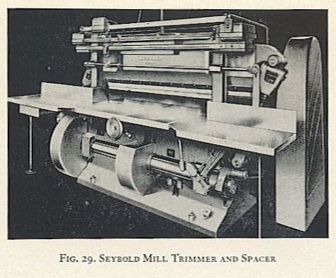
Seybold Mill Trimmer and Spacer. These machines are similar to the Series 6o except that they have no foot treadle for the clamp. They are of extra heavy construction for use in paper mills exclusively.
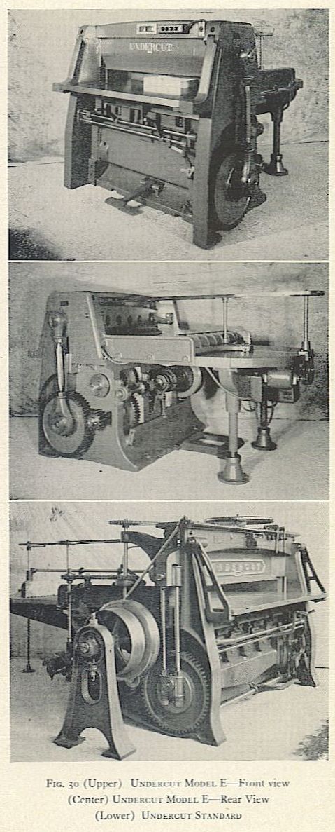
Undercut. Radically different from conventional paper cutters. the Undercut machine cuts with a guillotine knife which raises, sharpened edge up, from below the surface of the cutter table. The machine is made in two styles, Standard and Model E. both of massive construction for use in paper mills. The Standard is built in S sizes from 48 inch to 92 inch: the Model E in 5 sizes, 56 inch to 96 inch. The clamp is automatic, gear driven. A power driven back gauge is standard equipment on 56 inch and larger units.
Two hand starting levers control the operation of the knife. When the clutch is engaged the clamp is pulled down, compressing the paper. As the knife starts its cut, the front of the cutter table swings forward to allow theknife to rise. This swinging motion bends the paper at the point of cut and carries the cut paper away from the path of the knife. The knife ascends until it touches the cutting stick which is held in the clamp, then it descends to its starting position below the cutter table. The front of the cutter table returns to cover the knife, clamp pressure is released, and the cut stock is ready for removal. Complete instructions for operation, adjustment and maintenance are available from the Smith and ‘Winchester Manufacturing Company, South Windham, Connecticut.