
CHAPTER VIII
Specialty Machines
Brackett Safety Trimmer. This trimmer is a single knife, guillotine machine used for large scale cutting of bound or flat work which requires many cuts to each lift of stock. Each setting of the back gauge is controlled by a spacer shaft equipped with guide stops which are adjusted before cutting the job. After the stops are set the operator places the lift against the gauge and presses a hand grip which moves the gauge forward until it touches the stop.
An oil brake brings the gauge to a smooth stop without jarring the lift. The solenoid controlled safety releases the control handle allowing the operator to trip the knife and make the cut. See figures 31a and 31b.
Pressure on the hand grip moves the gauge to begin the next cut. Meanwhile, finished work and trimmings are deposited on a conveyor belt and carried to the back of the machine as shown in figure 31c. Further operations necessary on trimmed work can be done at work stations at the rear of the machine. Trimmings left on the conveyor belt drop into a trash bin, figure 31d.
A mechanical hold down device, pictured in figure 31e, is provided for holding stitched work against the back gauge and reducing swell caused by the stitches. The device also is used on small work as a precaution against the operator getting his hand too close to the clamp.
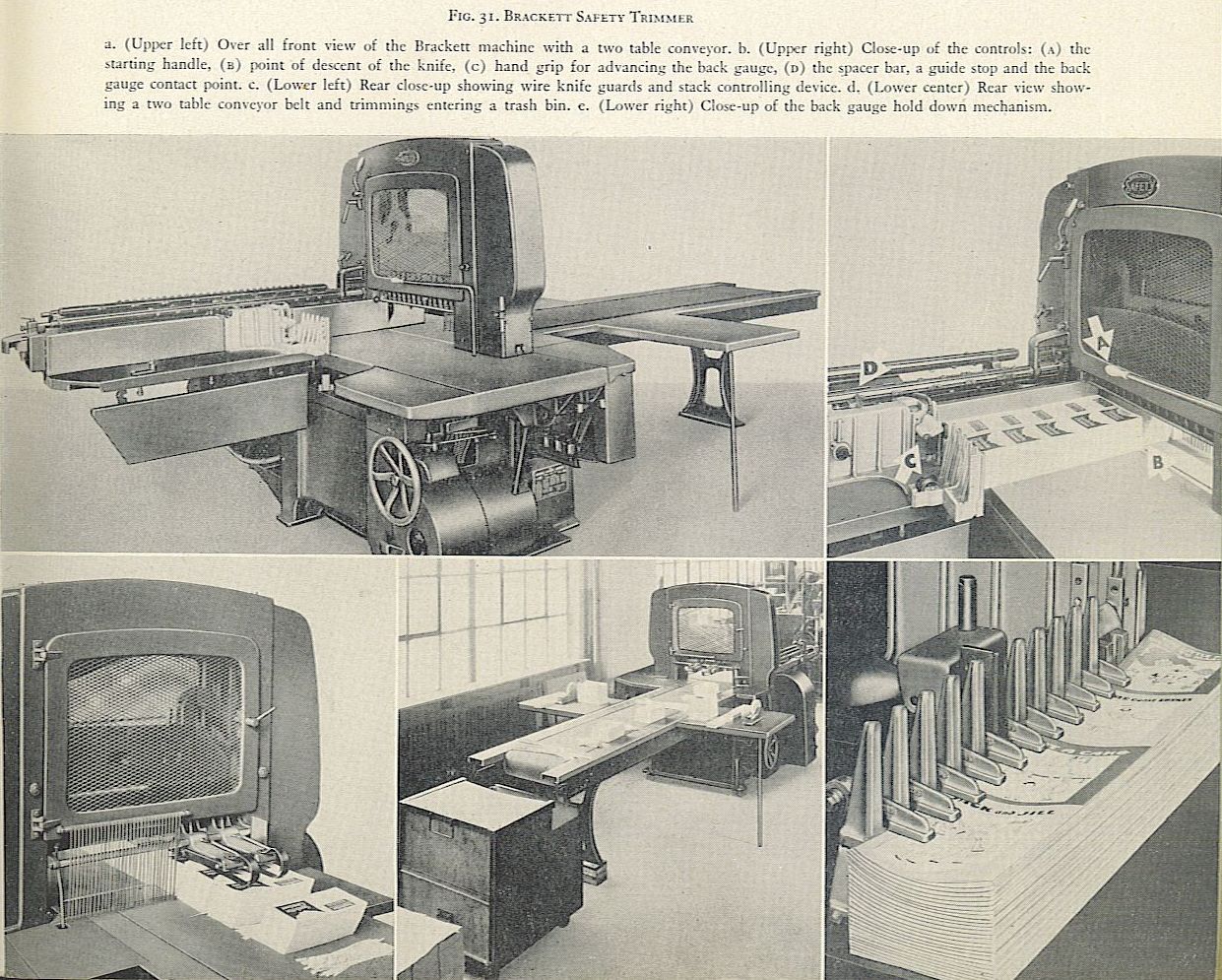
FIG. 31. BRACKETT SAFETY TRIMMER
a. (Upper left) Over all front view of the Brackett machine with a two table conveyor. b. (Upper right) Close-up of the controls: (A) the starting handle, (a) point of descent of the knife. (c) hand grip for advancing the back gauge, (o) the spacer bar, a guide stop and the back gauge contact point. c. (Lower left) Rear close-up showing wire knife guards and stack controlling device. d. (Lower center) Rear view showing a two table conveyor belt and trimmings entering a trash bin. c. (Lower right) Close-up of the back gauge hold down mechanism.
Workmen at the conveyor in the rear of the machine are protected from the knife by wire guards. A controlling attachment holds the cut stack as it is pushed on to the conveyor. as shown in figure 31c. Standard equipment includes an automatic hydraulic clamp and a knife changing device. Back gauges are made in 25, 38 or 50 inch sizes. Maximum width is 25;4 inches; maximum height of pile, 6 inches; speed 64 strokes per minute. An 18 inch conveyor is standard on 25 inch guide machines, and a 9% foot conveyor with two tables for 38 and 5o inch guides. Conveyors may be lengthened in 8 foot sections. For complete details see Instructions for Installation, Operation and Service of the Brackett Safety Trimmer, the Dexter Folder Company, 330 West 42nd Street, New York 18, New York.
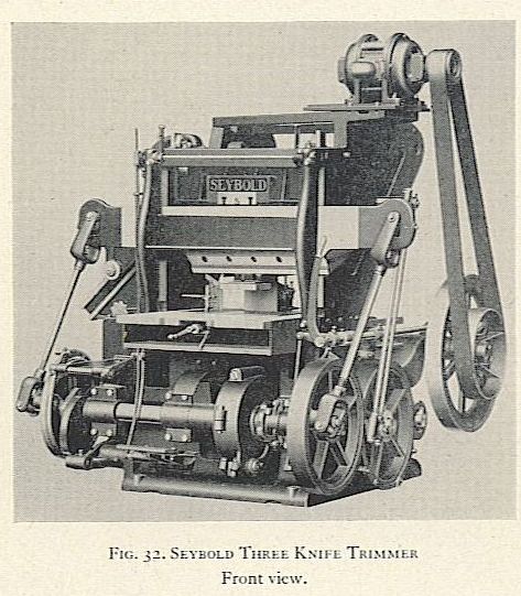
FIG. 32. SEYBOLD THREE KNIFE TRIMMER
Front view.
Seybold Three Knife Trimmer. The three knife trimmer is a half-way step between single knife machines and the automatic, continuous trimmer. It uses the guillotine principle and is semi-automatic in that it requires an operator to place the stack, pull a starting lever, then remove the trimmed stack and the trimmings. For operating sequence see figure 33. The machine is used for trimming sewed books and stitched magazines and pamphlets on a scale too large to be handled by a single knife cutter, vet not large enough to merit use of a continuous trimmer. Accuracy of the work is attributed to the fact that the entire operation is completed with but one application of clamping pressure.
Maximum trim size is 24 x 16 inches: minimum size, 5.14 x 2 sif: inches; maximum height of pile. 6 inches: maximum speed, 20 curs per minute; equipped with non-repeat safety device and overload release. Made by the HarrisSeybold Company, 4510 East 71st Street. Cleveland, Ohio.
Seybold Continuous Trimmer. This trimmer is completely automatic, an operator being required only to place jogged, untrimmed stacks in the feed trough or conveyor. The stack is then carried into the clamping mechanism which holds each stack under constant pressure throughout the trimming operation.
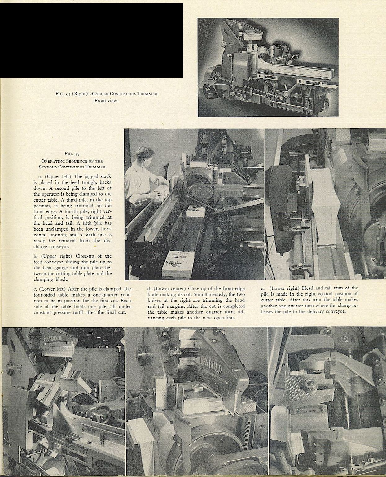
FIG. 33 OPERATING CYCLE OF THE THREE KNIFE TRIMMER
(Upper) After the work is positioned against the back and head gauges, the starting lever is pulled and the clamp descends to compress the pile. Full pressure is applied over the entire surface of the pile which remains clamped until all three sides are trimmed. The safety guard, not shown here, descends to insure that the workman has withdrawn both hands. (Center) Two knives descend together and trim the heads and tails. (Lower) As soon as the two knives have risen above the pile, the front knife descends and trims the front edge of the stack. When the front knife rises above the pile, the clamp is released and the safety guard rises from the front table so the trimmed stack and trimmings may be removed.
After the trimming is cornpleted clamp pressure is released and the stack is dropped to a delivery conveyor. For detailed operating sequence see figure 35. Uses of this machine are limited to trimming extremely long runs of sewed books and bound magazines.
Minimum trimming size is 4 x 6 inches: maximum,
12 x r6 inches: maximum height of pile, 6 inches; speed, 24 cuts per minute: trimmings removed by suction. Made by the Harris-Seybold Company.
FIG. 34 (Right) SEYBOLD CONTINUOUS TRIMMER
Front view.
FIG. 35
OPERATING SEQUENCE OF THE SEYEOLD CONTINUOUS TRIMMER
a. (Upper left) The jogged stack is placed in the feed trough. backs down. A second pile to the left of the operator is being clamped to the cutter table. A third pile. in the top position. is being trimmed on the front edge. A fourth pile, right vertical position, is being trimmed at the head and tail. A fifth “pile has been undamped in the lower, horizontal position, and a sixth pile is ready for removal from the discharge conveyor.
b. (Upper right) Close-up of the feed conveyor sliding the pile up to the head gauge and into place between the cutting table plate and the clamping block.
c. (Lower left) After the pile is clamped. the four-sided table makes a one-quarter rotation to be in position for the first cut. Each side of the table holds one pile, all under constant pressure until after the final cut.
d. (Lower center) Close-up of the front edge knife making its cut. Simultaneously, the two knives at the right are trimming the head sn(1 tail margins. After the cut is completed the table makes another quarter turn, advancing each pile to the next operation.
(I.ower right) Head and tail trim of tile pile is made in the right vertical position of cutter table. After this trim the table makes another one-quarter turn where the clamp releases the pile to the delivery conveyor.
Sheridan Straight Line Continuous Trimmer. The second type of automatic trimmer made by the Sheridan company operates on the guillotine principle. Its primary uses are long editions of side stitched magazines or sewed books. The stacks to be trimmed are fed into a V shaped trough with the jogged backs resting against one wall of the V. A conveyor carries the stack along to the first station where clamp pressure is applied and the front trim occurs. Clamp pressure is released, the stack is carried to the second station, a second clamp pressure is applied and the head and tail trim is made with a single stroke of two knives. Clamp pressure is released and the trimmed stack is delivered at the end of the machine by the conveyor.
Minimum trimming size is 4 x 6 1/2; inches; maximum size, 12 x 16 inches; height of pile, 5 to 6 inches; speed range, 20 to 35 cuts per minute; trimmings removed by suction.
Sheridan A-T Single Book Trimmer. This machine operates in combination with either the Sheridan Inserter or Sheridan Tabloid Gathering-Stitching-Folding machine and is used to trim long-run editions of national magazines. The machine utilizes the shears principle, having a stationary lower blade and an upper blade in contact that descends to make the cut. There are three sets of blades, one for each trimmed side of the magazine.
After being gathered and saddle stitched, the individual book passes along conveyors into the trimmer where it is trimmed automatically on three sides. At the first cutting station the magazine is clamped and the front edge is trimmed. At the second cutting station the head and tail trim are made with one stroke. The clamp is released and the finished product is delivered.
Maximum trimming size is 16 x 12 inches; minimum, 8 x 6 inches; maximum thickness, 3/16 inch. saddle stitch only: operating speed, 90 to iio per minute; trimmings removed by suction. Manufactured by the T. W. and C. B. Sheridan Company, 135 Lafayette Street, New York 13, New York.
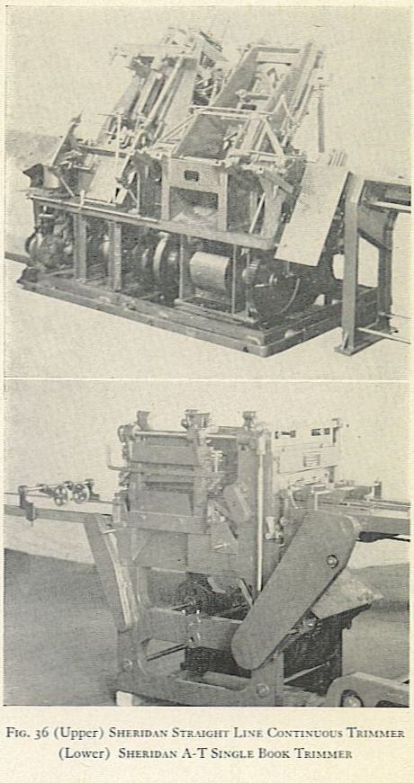
FIG. 36 (Upper) SHERIDAN STRAIGHT LINE CONTINUOUS TRINIMER.
(Lower) SHERIDAN A-T SINGLE BOOK TRIMMER